
Once someone in motorsports finds out you know something about aerodynamics, one of three questions tends to come to the fore of their minds: "What's the best wing I can get?", "How do I make more front downforce?" "How do I cool off all this 10 pounds of heat generating mechanica I've stuffed into a 6 pound bag?" For this post, and possibly the next post, we're going to focus on the first of those questions... but perhaps not in the way you expect.
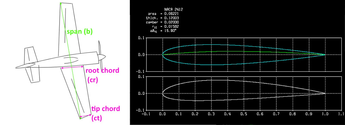
The obvious answer to "what's the best wing?" I've already answered in the previous two posts - effectively that: there's no such thing, and any design is a selection of compromises whose balance tips between rules, budget, and "fashion." In order to evaluate those compromises, though, we should understand the fundamentals of what a "wing" is. Mainly that it is a surface with span (i.e. side-to-side width), chord length (i.e. front to back length), thickness and contour along the chordline (often referred to as a 'foil'), that when provided a flow velocity and angle creates a circulation of air.

If that seems horrifically generic, just hold on to your gurneys. Beyond the conviction that there's no single best wing, I'll also argue that many things are "wings," and thus there is no "one true wing" shape. Similarly, there is no single "one true foil shape". Some shapes generate more lift over a broader range of angles of attack, some make lots of lift and lots of drag.
For example, and not exhaustively, these are examples of Wings:

This might be a wing:

One parameter of a wing's geometry that I neglected to note above is a term that helps aerodynamicists predict/account some of the flow characteristics of the wing based on its span, chord, and taper (usually where the tip {far end} chord length is smaller than the root {chord length where it meets the plane's body/centerline} chord). It's formally described as:
AR = (span^2) / Area
This dimensionless value helps aerodynamicists determine how much drag the wing will create based on the vortex created due to the generation of lift. Or, said another way, it's a convenient short-hand for gauging the efficiency of a wing... especially as the load or angle increases. This efficiency also influences how much other aspects of the wing's geometry influence the performance of the wing. As the AspectRatio dwindles below ~3, the flow's tendency to create vortices goes up and dominates the flow state. When the AspectRatio goes up, the wing's performance more closely matches a 2D simplification of wing flow analysis that only look at the foil contour of the wing.*
Now that we've brokered our first equation, I figure we should continue on in this post with some of the other primary principles, laws, and equations we'll be encountering in the course of this blog. Based on that, we should probably start with the beginning... a principle that predates the first flights of our race by 50 years.
Bernoulli's Principle coupled with the Continuity Equation
The main takeaway from Bernoulli's we'll interact with is the concept that in a flow with constant energy (i.e. without mechanical or thermodynamic influence), that when the flow passes through a region of lower pressure, the speed of the increases (and vice versa); which can be coupled with the Continuity Equation's perspective that an increase in area of a duct will lead to a reduction in speed of the flow in the duct... and as we know now that also means an increase in pressure.

This is a dimensionless quantity is helpful in comparing and accounting for flows of different sizes and speeds (including changes in density and viscosity). It allows for tests in water tunnels to be correlated to full scale aircraft in air; and it's also one of the ways that aerodynamicists account for how bees fly "with too little wing area."
Re = ( Fluid Density * Flow Velocity * Object Length ) / Fluid Viscosity
Full size aircraft usually operate well into the "millions" of Reynolds Number. Model aircraft and motorsports frequently fit into the transitional 100,000 to 1 million range, that's known as the "low Reynolds Number range/regime"... where the thin 'skin' of flow near the surface of a body (i.e. the boundary layer) transitions from Laminar to Turbulent flow more quickly and unsteadily. The closer to 100,000 a surface is operating, the lower the maximum lift it will generate, and the the more drag it will generate.
This will be generally less important the others. I mention it mainly as a reminder that we can use fundamental aspects... temperature, pressure, gas constant... of the gas being studied (i.e. "air") in order to determine the density of the gas at the time its being tested. And, we've already seen its use in determining ReynoldsNumber and is a fundamental component of pulling this all together to calculate the forces on an object via the fluid flowing around it...
Generalized Calculation of Fluid Dynamic Forces
Force = 0.5 * Density * (Speed^2) * Reference Area * Coefficient
One thing to note, is that pressure is not listed for the calculation of Lift/Drag. You'll often times hear "this positive/negative pressure here means there's lift/drag/downforce". And yet, we don't find the pressure directly presented in the force calculation. Instead, the coefficient (be that Lift, Downforce, or Drag) is a non-dimensional representation of the pressure acting on the surface. Although, if we look back at Bernoulli's, we could also say that the coefficient is a non-dimensional representation of the flow accelerating and decelerating as it passes along the surface.
This strikes at a fundamental complexity of aerodynamics that is often absent in discussions of motosports aerodynamics you'll find online: there is no singular agreement for why when the fluid** encounters an object that the fluid speeds up and that the pressure drops. Primarily we "just know that it does". That is, we know that that happens, but we don't know why; and we don't know which is actually the reason this phenomenon means airplanes fly, and race cars stick to the ground better.
If you want to explore our lack of understanding lift, I highly suggest this Lecture by Doug McLean to University of Michigan Aerospace Engineering Department (youtube link).
Along the same lines, while it's tantalizing to explain lift (or, more commonly in motorsports, downforce) through the simple concept of "negative pressure on one side of a surface means high pressure on the other side of the surfaces pushes the object away"... I'd contend it's important to keep in mind that pressure is important and valued primarily because of how easily it can be measured (this ability to measure it means that one can then calculate the integral of the pressure over a surface, and come up with what the "coefficient" is; which is something that most Aerodynamics majors have to do in an Aerodynamics Lab component.). Whereas the flow velocity and direction is as important to determining fluid dynamic performance... however it is exceedingly difficult to measure and categorize in "unconstrained" flows (i.e. flows that are not contained within a walled structure, or near a ground surface)... in part because all of the ways we know to measure it end up impacting the flow itself.
Most of the above is a brief exposition on the dynamics of fluids. It's brief in part because Scott and I see value in breaking these posts down into "manageable morsels". For your benefit, and our own. This is far from a rigorous explanation of things, and I'm sure other aero professionals may find issue with some of the above, and/or oversimplification of things. However, there is a great value in limiting the scope of the these technical explanations as we begin our journey. If I have misstated something, please let us know, and we'll make a correction.
Since we're talking about wings, I think we should make time and space to discuss a simplification that is useful in highlighting the discussion of "what is a wing"/"there is no best wing". And that is to consider the wing's fundamental simplification: the 2D longitudinal cross-section of wings, aka the "foil" shape.
Foils seem to be a relatively misunderstood thing, so we'll begin by looking at the nomenclature of 2D-foil sections. This is an image of a "common" low-speed aircraft foil section: the NACA 2412 as plotted by Xfoil:

It has the following geometric characteristics:
- Maximum thickness of 12% of the chord***, placed at 30% chord station (all NACA 4-digit series foils have their maximum thickness at 30% chord).
(this visualized via the top graph's blue outline, plus the "thick." value at the top)
- Maximum camber of 2% of the chord****, placed at 40% chord station*****.
(this is seen in the top graph's green curve, as the distance away from the chordline; plus the displayed "camber" value).
- Leading Edge Raidus of 1.58%chord
-
A trailing edge angle of 15.9deg
I'd like to point out that except for the trailing edge angle, all the provided values are presented in relation to the unitary chord length (generally represented as 'percent chord'). I'm stressing this because I've seen the camber of a foil erroneously labeled in "degrees of camber" several times. I can understand how the camber of a foil could be confused as being in degrees, but I'm hopeful that knowing that its value is in %chord will be beneficial if/when we begin analyzing comparing foil shapes in the future.
If we look at this 2D foil, and analyze it at two different angles of attack, in this case the value for L/Dmax (the maximum ratio of Lift:Drag) and Clmax (the Maximum Lift {downforce} Coefficient attained in in a search of variable Angle of Attacks) we'll find some interesting examples of what's termed "The Kutta Condition":


I bring this up, in advance of a future discussion, about motorsports terminology. Fundamentally, every object subject to unconstrained fluid flows (aka "free air") is a splitter. The geometry of the object, and the preconditions of the flow before it will determine where that split occurs. But, generally speaking, the more a front edge of an object is sharp (i.e. Leading Edge Radius), the worse that object will perform in terms of Lift (less) and Drag (more) {technically sharpness is negatively correlated to performance}, outside of a highly restrictive angle of attack range. For a visual example of that, one can turn to a "polar" analysis of a thin "splitter" or "plank" foil of 1% thickness, with a common simple 12% symmetric foil******:

"Sharpness is negatively correlated to performance" may sound like an excellent Axe Metal Tribute Band, more than a relatable term de'art. Think of it as: the sharpness of an object limits the range of angles that it will generate downforce without large amounts of drag. In the image above, the green curve on the right is limited in the angle (x axis) it can go to before the Lift (y axis) begins to turn back down in comparison to the red line (which is the NACA 0012 foil). Meanwhile, the Drag (which is x axis on the left plot) is higher for the green "plank" foil than all the drag of the NACA0012 foil (green)...except when the NACA0012 foil is nearing the maximum Lift (y axis of the left chart). If we look even closer at the Lift-to-Angle plot (right), we'll see that there is a lift (downforce) benefit beginning at 3.5deg Angle of Attack (AoA). This benefit is being seen even when JavaFoil and Xfoil will most likely over-predict the plank's Lift performance, since both of these codes are simplified in being their capability to look for Laminar Separation Bubble (LSB)... which sharp foils at low Reynolds number will have.
There are rare cases, mainly thanks to proximity to the ground, where this tradeoff can make some sense. But, often times, being able to broaden the leading edge radius will mean the object will generate more downforce with lower drag over more angles of attack... which considering how much race cars pitch/roll/yaw... not to mention be impacted by variable winds, and track surface undulations... means more downforce generation over multiple angles is a value that should be of considerable consequence. But that, perhaps, is a study for a later post.
Until the next time,
Tim "Sleepyhead the Buffalo" Miller
Standard Buffalo Post Scripts:
Gratias tibi ago:
I am not a Lone Buffalo in this endeavor, so I'd like to express my appreciation to Scott Robertson, and Beverly Miller in assisting in the publication of this post.
Caveat:
I am an Engineer, and a Buffalo. I do not have an English Degree. While an effort has been made to catch any grammatical mistakes, there are bound to be some. Similarly, there's every chance I've screwed up some math somewhere. Hopefully, you can look past any of the compositional/grammatical errors, to find value within. If there are mathematical errors, feel free to engage us constructively via social media, or one of the options available on our Contacts Page.
Footnotes:
wing image sources:
https://pxhere.com/en/photo/557837
https://www.publicdomainpictures.net/pictures/80000/velka/stampe-biplane.jpg
https://upload.wikimedia.org/wikipedia/commons/thumb/9/90/Piaggio_P-180_Avanti_Rennes_2010.jpg/1920px-Piaggio_P-180_Avanti_Rennes_2010.jpg
via: https://web.archive.org/web/20070310224215/http://www.guillow.com/kitimages/300/prod_det_30.jpg
https://upload.wikimedia.org/wikipedia/commons/thumb/e/e6/Eclipse_program_QF-106_aircraft_in_flight%2C_view_from_tanker.jpg/300px-Eclipse_program_QF-106_aircraft_in_flight%2C_view_from_tanker.jpg
https://de.wikipedia.org/wiki/Lee-Richards_Annular_Monoplane#/media/Datei:Lee-Richards_Annular_Monoplane_No_I.jpg
https://c4.wallpaperflare.com/wallpaper/846/187/742/acura-nsx-gt3-acura-nsx-gt3-race-liveries-2017-hd-wallpaper-preview.jpg
* It should be noted, though, that the main reason the relationship about efficiency of a wing is presented in terms of "AspectRatio" and not simply "span length" (which really is the dominant term here), is because holding the wing area constant is important for making sure the comparison is happening at the same lift/downforce condition. Otherwise, if one were to increase span, while holding everything else the same, then the wing has more area. Thus this new wing either makes more lift, or operates at a lower lift coefficient.
** this is for fluids interacting with objects at velocities below which the pressure wave's disturbance can be resolved before the arrival of the object {i.e. so called "subsonic"}
*** this 12% of chord maximum thickness is represented by the '12' in the 2412 name.
**** this 2% chord camber is represented by the '2' in the 2412 name.
***** this 40% is represented by the '4' in the 2412 name.
****** these are the foil geometries used for this polar comparison: